yep, youre not reading those without some soldering involved.
Not a stranger to de-soldering and reading/writing to IC/EEPROMs. Had to do so to resuscitate my W8 FIS cluster. Have a hot air rework station now. I guess I'll open them up and have a look for the likely culprits. Assuming the EEPROM will be a small chip like the cluster and ME7.x ECUs. What kind of chip am I looking for to read flash info from?
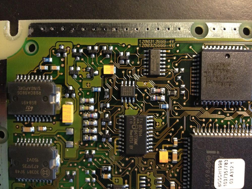
Top of the PCB

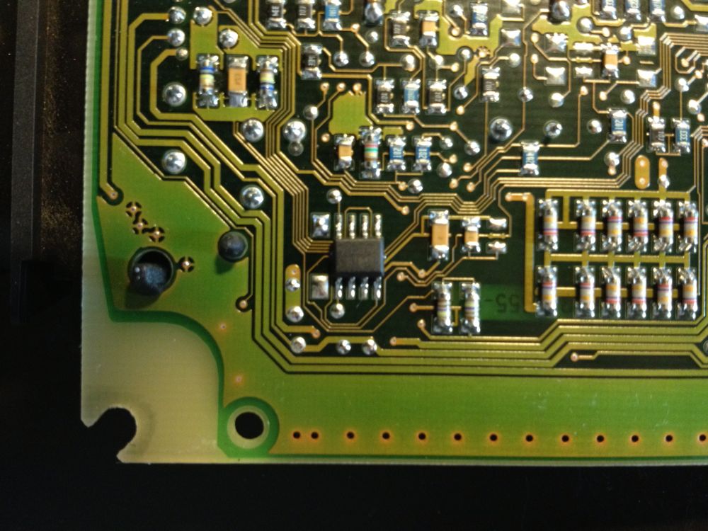
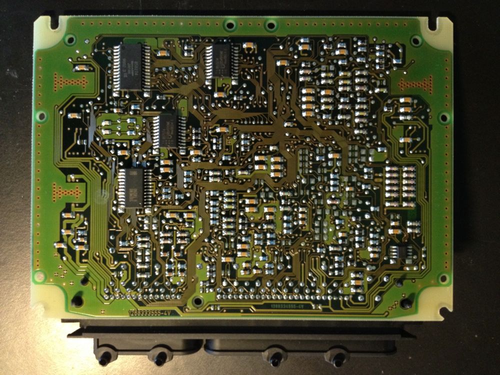
Bottom of the PCB:
For EEPROM, these two are the likely candidates -
This one is on the top of the PCB, and the markings are 30132 BN806 A5847:
This one is on the bottom of the PCB, and the markings are very difficult to read: