Hmm. Let's look into it a bit;
The best place to measure the air/fuel as an accurate interpretation of lambda post combustion, is pretty much in the port or just entering the runner, obvious downside being the temperature of the gas and additional coking which would subsequently lead to maladjustments due to incorrect readings. There's also turbulent over laminar flow to consider and sensors being used, strategy taken etc.
First point then would be that on these conversions. Do you have your sensors nearer the ports than factory locations?
So turbulent v laminar flow and sensor location. Well, main thing is to understand that you want the best reading from 3 cylinders and as the oem ones, so first port of call is making sure that the sensor location is getting the full read of all cylinders it is supposed to, 2 front 1 back and vice versa, obv dep on manifold and that the location is sound. If you get turbulent flow at the collector location or any location which is the sampling point - well, nothing likes turbulent flow!
Thirdly, temp and coking. Well, simply put, you'll get more coking in the manifold so I'd check them more frequently so you don't get maladjustments happening due to bad readings.
Temp then, the bane of which people speak!
According to the 4.2 LSU documentation, the sensors can run sustained 930*C temps with a 1030*C max for short periods. I'm not sure of sensor differences but I'm inclined to believe these are applicable, at least for this example, for the mk5 R32, as the manifold lambda correction/BTS maps have a 900C limit;
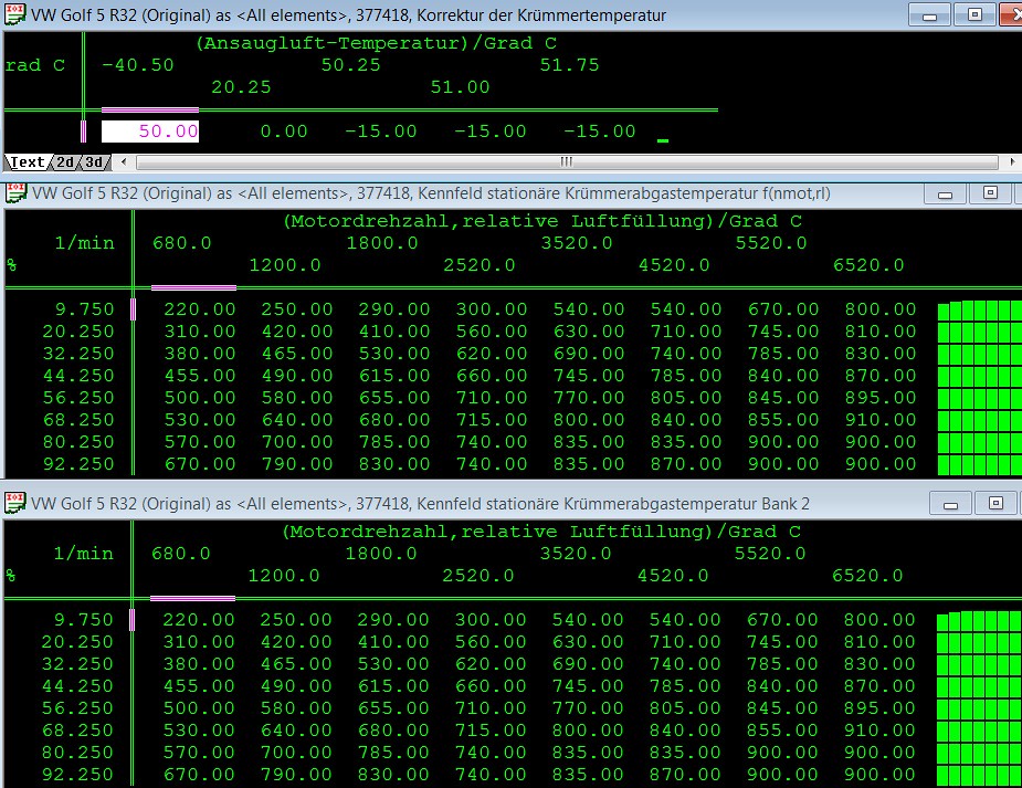 mk5 R32 Stationary manifold exhaust gas correction
 by
Rick B, on Flickr
Plenty of correction aspects you can play with in the later ecu's, can also do similar BTS in older ones, just not quite as detailed - Audi tend to get things 1st in their ecu's so age dep. really on yours on what maps are in, I've not turned it into a def file yet.
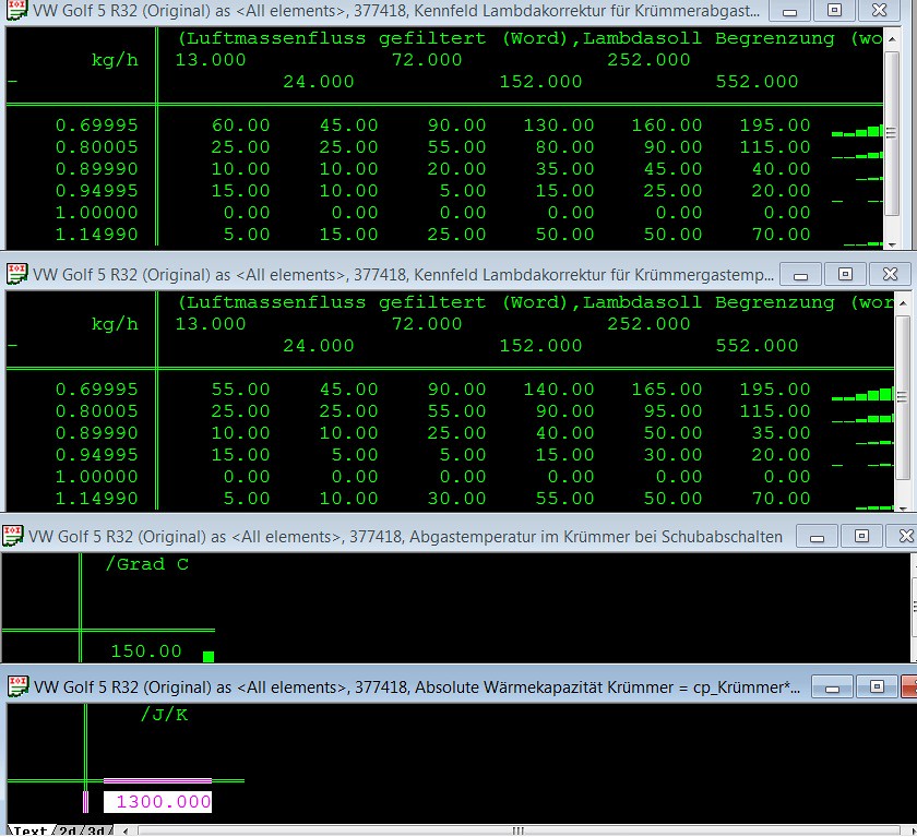 mk5 R32 Manifold exhaust gas 2
 by
Rick B, on Flickr
What is interesting to note also is the "hex temp" of 570C in that Bosch LSU doc and lo and behold there's a little sneaky map in the mk5's that accounts for that component protection too!
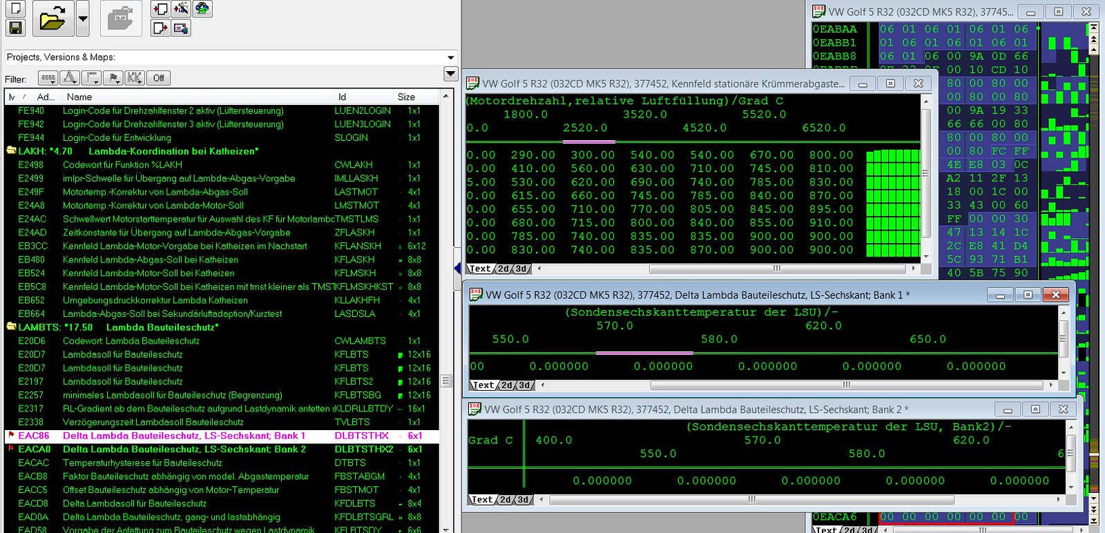 mk5 R32 Lam exh comp protection
 by
Rick B, on Flickr
BUT.....you needn't piddle about with these things for a simple base map set up! Back on track;
When you underscaled your hfm did you check/make sure any representative maps were changed accordingly, check any possible MIL problems?
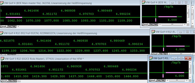 MLHFM & Min mass V6 R32 mk4 mk5
 by
Rick B, on Flickr
As any bendy intake VR6 12V owner will tell you, "these maf's don't like turbulent flow!" - which is why Bosch upgraded to the glass/ceramic substrate HFM 5 versions (if you're just looking into these things there's a guide I did from Bosch info in the noobs guides section, which explains how they started to upgrade things for evolutions from VR6 12V to R32 and the tuning basics) -so check your pulsations maps if you haven't done so already.
Let's see, what else - ignition is obviously different NA/FI and if anyone's reading is just setting out, I'd suggest looking at the ignition maps between various NA/FI vehicles of a similar nature to get an understanding. Main maps and, importantly, limit's as you are going to meet them at some point. I'd try and get a list of the min/max and representative values together as you'll need to change some of them at some point both at the start and as you tune - not just in ignition but every area really - a good def file will make things a lot easier!
Main thing with these is formulating a strategy and sticking to it. WDKSOM tells you about how it's all tied together somewhat, so you have DK (throttle angle), torque and idle - you're adding air, so look at all the luft/air maps to see what may or may not be applicable. I and others have mentioned above aspects to consider like the 02 sensor (ATM aspects), the usual injection but as you're essentially modelling this additional air/density what compensation aspects and BTS tuning do you need to think about? Ultimately anything sort of SY_TURBO based in the FS - just, do you need to do something when you can compensate for it?
I'm trying to get you into the habit of "systems thinking" so how are things connected, what do you have, what is missing, what build mods have you made over original, how can you compensate for those things etc?
So good def, ES/BTS/KR/ZU/LLR/DK - once you get your head around that, then what about part additions/delete's etc and what effect will they have?
After the simple flash side in those ways, then it's then onto choosing a different strategy, iop and hfm sensor extensions, patches if/as/when required (don't mix the strategies up, what seemed to be happening here) - then if you have a coding background, further reverse engineering/dissasembly and patching;
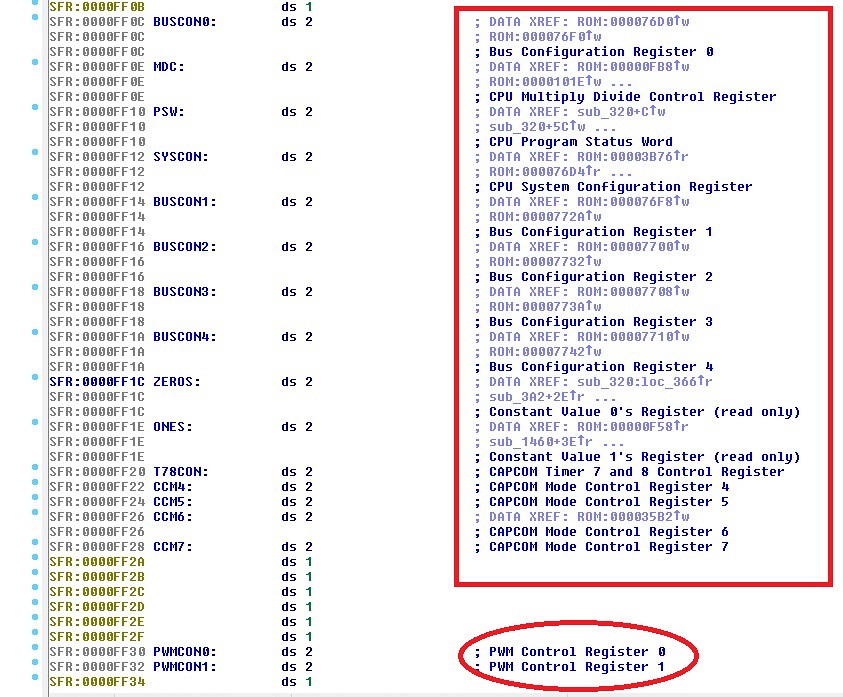 mk4 r32 pwm sfr registers
 by
Rick B, on Flickr
I think what should be mentioned also as I have found, is the interaction between flashing/data modding tools and the various ecu's. There's 8 C167 revisions, 3 used on the 2.8-3.2 that I am aware of and tools seem to act differently in terms of data transferral, probably a crc thing, but some seem to be able to sort that out and transfer data and some would end up bypassing.
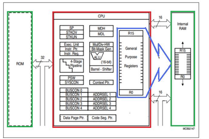 C167 CPU Layout
 by
Rick B, on Flickr
I put a "cheap tools" thread up in flashing area to try and see how the data takes a hold with them but most haven't gone this far, however I think testing things with max limit's like ignition angle, would give a good indication of flashing compatibility plus it's something needed. I'm interested in the electronic whizzes and those trying things with the cheaper tools and their turbo home brews to chip in.
Oh and P.S. - if you're rocking 2.8 24VT set ups, I'd look into a lot on flow, those little throttle body blades and smaller hfm's can cause limit problems far sooner than the R32's with their bigger set ups, take a look at flow across tb for example;
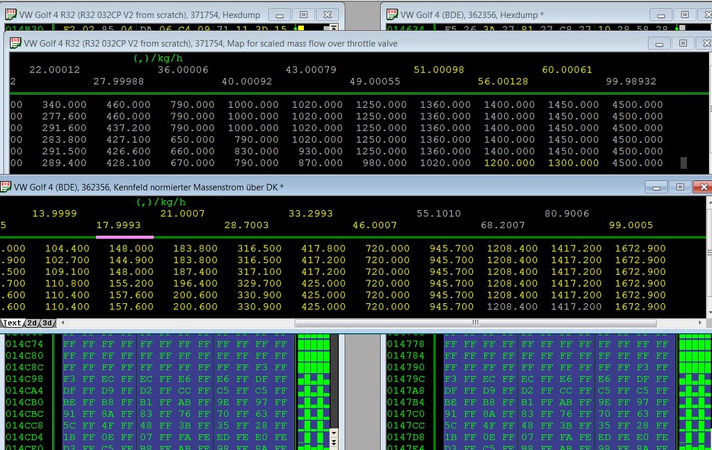 Flow across TB 032CP v BDE
 by
Rick B, on Flickr
Anyway, my 2p, hope it helps!