Pages: 1 2 [3] 4
Author Topic: ECU boost control on compound turbos - thoughts?  (Read 28797 times)
elRey
Hero Member
*****

Karma: +32/-1
Offline Offline

Posts: 565


« Reply #30 on: February 03, 2017, 01:48:28 PM »

Only shortcoming of the water wheel analogy is that water can't compress. If it could, and you compressed the water to 2x it's original density, you would then be able to pass twice the amount of water past the wheel at the same wheel speed (ignoring temperature).  Stilling wondering if my previous post is what prj is referring to.
« Last Edit: February 03, 2017, 01:51:41 PM by elRey » Logged
fknbrkn
Hero Member
*****

Karma: +186/-24
Offline Offline

Posts: 1456


mk4 1.8T AUM


« Reply #31 on: February 03, 2017, 11:15:19 PM »

Why would I want to destroy my turbo by un plugging the waste gate line. Smiley
destroyin turbo? lol
no need to full wot run, only spooling difference
cmon
do it
Logged
TijnCU
Hero Member
*****

Karma: +60/-4
Offline Offline

Posts: 690


flying brick


« Reply #32 on: February 04, 2017, 09:51:57 AM »

I understand your point of view, I guess it depends if there is a direct relation between volumetric and mass flow rate or not. It is confusing that different units are used between manufacturers to describe compressor performance as well. In any case, my comments are only meant as help for your project to succeed.
 For boost control it may be sufficient to only monitor the large turbo pressure for control, the small turbo needs to open all gates as soon as useable boost is made on the large turbo in my opinion. No need for high boost if you can have proper flow, keep temps low and timing high :-)
Logged

elRey
Hero Member
*****

Karma: +32/-1
Offline Offline

Posts: 565


« Reply #33 on: February 04, 2017, 10:19:43 AM »

Thanks. I'll say this when looking at compressor maps: they are corrected for sae or at sea level. Once you change P1, you have to recalculate/recalibrate the x-axis flow. The axis values will shift left or right depending if you are correcting for a higher or lower P1. The big turbo is increasing the P1 for the small turbo map. Single turbos, it's atmosphere or whatever pressure pre-compressor which may be lower due to filter restriction.

That's what I believe causes a lot of confusion around this topic.

As for small turbo boost control, what about the majority of driving conditions? e.g. partial throttle or even just spooling? I have to control the small turbo at some point even if it's not at the top-end WOT.
Logged
TijnCU
Hero Member
*****

Karma: +60/-4
Offline Offline

Posts: 690


flying brick


« Reply #34 on: February 04, 2017, 11:41:00 AM »

How about a more big turbo oriented control, you can use throttleplate angle for part throttle while the k03 is at 95% dc. You could run the hp gate from lp pressure to make it switch to bypass mode automatically and use lp Watergate for further control. Or if you can use 2 n75 you can keep k03 iwg control for low end and fix n75 duty to 0% from a certain pressure up and take over with lp n75 control?
Logged

fgtskofd
Full Member
***

Karma: +0/-13
Offline Offline

Posts: 91


« Reply #35 on: February 04, 2017, 01:54:59 PM »

destroyin turbo? lol
no need to full wot run, only spooling difference
cmon
do it
I already have lost a few extended  tips off my billet turbine wheel,(boost leak over speed), I since turned them off completely and sent away for Re balance.
Logged
Rick
Hero Member
*****

Karma: +63/-4
Offline Offline

Posts: 704


« Reply #36 on: February 04, 2017, 02:29:18 PM »

elRay is correct here.

The exhaust side 100% needs a bypass, the compressor doesn't.  However, the power available is less than if the larger turbo is used on its own.

The large turbo has compressed the air before it enters the small turbo, so its volume for a given mass is much smaller than it would be entering at atmospheric.

Rick
Logged
elRey
Hero Member
*****

Karma: +32/-1
Offline Offline

Posts: 565


« Reply #37 on: February 04, 2017, 03:11:19 PM »

However, the power available is less than if the larger turbo is used on its own.

I will not argue that, but what about total area under curve / driveability compared to any one 'reasonably price' turbo?

« Last Edit: February 04, 2017, 05:42:02 PM by elRey » Logged
Rick
Hero Member
*****

Karma: +63/-4
Offline Offline

Posts: 704


« Reply #38 on: February 04, 2017, 04:06:20 PM »

Better for sure.  Have experienced it on 4G63 and Cosworth YB but with basic mechanical control.

Rick

Logged
Audi100LS
Newbie
*

Karma: +0/-1
Offline Offline

Posts: 17


« Reply #39 on: February 04, 2017, 06:45:17 PM »

From my experience in Diesel compound setups this is set up properly (Mainly working on 6.4 Powerstrokes).

It's a common misconception that the compressor is limited to some arbitrary flow.  Compressed air is entering the smaller (HP) compressor.  The small compressor is simply multiplying this incoming pressure, and further compressing it to a higher pressure.  Plot this out on a compressor map and you'll see it still falls in line. 

However, the engine would be limited by how much air can flow through the hotside of the HP turbo.  elrey has addressed this by running the wastegate open all the time on the HP turbo.

Diesel guys have been doing this for years without compressor bypasses.  I think people are mixing up sequential and compounding turbos.  In a compound setup the LP isn't "coming on line" like it does in a sequential set up.

Now I may be wrong, but I think the best way to go about this would be to limit the HP to a safe pressure ratio (say 2) and then control boost on the LP as you normally would conventionally
Logged
elRey
Hero Member
*****

Karma: +32/-1
Offline Offline

Posts: 565


« Reply #40 on: February 04, 2017, 07:05:33 PM »

How about a more big turbo oriented control, you can use throttleplate angle for part throttle while the k03 is at 95% dc. You could run the hp gate from lp pressure to make it switch to bypass mode automatically and use lp Watergate for further control. Or if you can use 2 n75 you can keep k03 iwg control for low end and fix n75 duty to 0% from a certain pressure up and take over with lp n75 control?

If I'm controlling both turbos WGs with 2 N75, 95% for small and big turbo at low end, and then xx% for big turbo at top end, why not just control both all the time???  0% to small turbo is still controlling it.

For small turbo, I can picture a kfdmix with 0% on the top-end. Right now, with 10% big turbo duty, small turbo duty automatically goes to 0% without me changing anything just due to PID control even with a ~95% kfdimx value.

The problem with making small turbo kfdmix 0% up top, is what if big turbo is not spooled yet? For instance when starting WOT already at high RPM or gear shifts? I would want small turbo to be 95-100% for the few seconds it takes big turbo to respool. So, a static kfdmix will not work for that situation.

I think I need an offset or factor map applied to small turbo's kfdmix output based on big turbo's current boost pressure.

Logged
TijnCU
Hero Member
*****

Karma: +60/-4
Offline Offline

Posts: 690


flying brick


« Reply #41 on: February 05, 2017, 02:58:38 PM »

Maybe that can be done with a second map and/or a threshold from LP boost before final HP n75 result is passed on. that would not be hard to code. for example if LP boost is less than xxxxmbar and load request is over xxx, replace HP n75 duty with 95% if you want it hardcoded or make a small calibration map from reqested load and actual boost that gives out a new dynamic n75 dutycycle.

Btw I hope you have the option to bypass the K03 hotside with a properly sized wastegate? That was what I was referring to with the mechanical control from LP turbo. Even in a K04 hotside, the exhaust has proven to be the real topend restriction and egt will rocket with large compressors. Can imagine that even with wide open iwg you will get backpressure and heat from the housing when that big compressor starts to pick up speed...
« Last Edit: February 06, 2017, 04:24:52 AM by TijnCU » Logged

ruan
Jr. Member
**

Karma: +2/-8
Offline Offline

Posts: 33


« Reply #42 on: February 06, 2017, 03:58:30 AM »

Thanks. I'll say this when looking at compressor maps: they are corrected for sae or at sea level. Once you change P1, you have to recalculate/recalibrate the x-axis flow. The axis values will shift left or right depending if you are correcting for a higher or lower P1. The big turbo is increasing the P1 for the small turbo map. Single turbos, it's atmosphere or whatever pressure pre-compressor which may be lower due to filter restriction.

mcorr = m*sqrt(T2/T1)/(P2/P1)

mcorr = Corrected Mass Flow (new x-axis)
m = Actual Mass Flow

P1 = STP Reference Inlet Pressure
P2 = Compressor Inlet Pressure

T1 = STP Reference Inlet Temperature (*K)
T2 = Compressor Inlet Temperature (*K)

Course the pain is that not every turbocharger manufacturer's "corrected" conditions are the same... Hence why some measure in mass flow rather than corrected volumetric flow, since that depends on the environment.
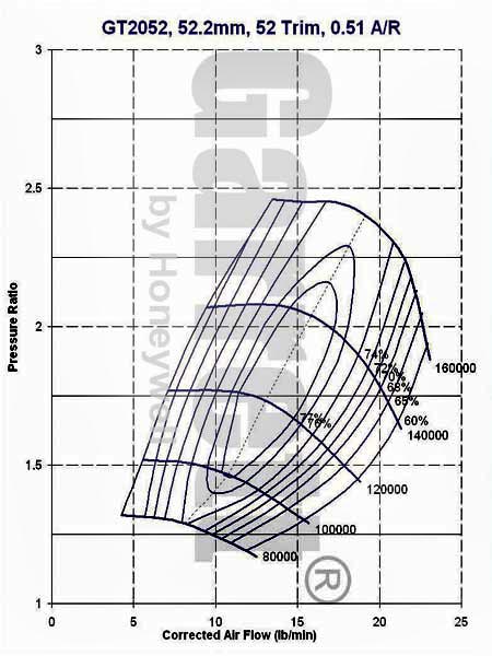


In this situation - taking into account what I said above - if the engine is capable of consuming 25lb/min, if you make the compressor inlet temperature 40*C and pressure 2bar(abs) on the inlet, when you correct the mass flow assuming, it's equivalent to that turbocharger moving 18.42lb/min.

25*sqrt(313/288)/(2/1) = 18.42lb/min

I'm fairly sure I'm correct here... Issue being you run up against the choke line quite quickly at low PR - look at the trend of the compressor shaft speed lines, at higher airflow, even at lower pressure, you're tending towards higher and higher compressor shaft speeds and into choke...
« Last Edit: February 06, 2017, 04:56:51 AM by ruan » Logged
Leonhard
Full Member
***

Karma: +29/-2
Offline Offline

Posts: 115


« Reply #43 on: February 06, 2017, 09:29:35 AM »

this might be helpful understanding gasoline R2S system:

http://www.turbos.borgwarner.com/en/press/knowledgeLibrary.aspx

"Regulated Two-Stage Turbocharging for gasoline Engines"
Logged
elRey
Hero Member
*****

Karma: +32/-1
Offline Offline

Posts: 565


« Reply #44 on: February 06, 2017, 09:41:46 AM »

this might be helpful understanding gasoline R2S system:

http://www.turbos.borgwarner.com/en/press/knowledgeLibrary.aspx

"Regulated Two-Stage Turbocharging for gasoline Engines"

That's a sequential system though.
Logged
Pages: 1 2 [3] 4
  Print  
 
Jump to:  

Powered by SMF 1.1.21 | SMF © 2015, Simple Machines Page created in 0.024 seconds with 17 queries. (Pretty URLs adds 0s, 0q)