|
_nameless
|
 |
« Reply #15 on: August 03, 2024, 08:56:41 PM »
|
|
|
i see what yor taking about with the tooling now. nver seen it before.. the drop probes and frame! sick!!!
The boot pin in the picture is the same as the pin 24, it's just another spot you can ground it that is more convenient. The cnf1 needs to be grounded as pictured with the 1k ohm resistor, like I said you do not need to use the resistor. Also, it's totally separate from the boot pin and do not cross ground them you may cause hardware damage |
|
|
|
|
 Logged
|
If you are broke or expecting free handouts DO NOT message me. I'll probably put you on blast if you do.
|
|
|
Matthewest91
Full Member

Karma: +0/-4
 Offline Offline
Posts: 109
|
|
« Reply #16 on: August 04, 2024, 08:22:47 AM »
|
|
|
 I believe my board is different than the picture. Sent from my iPhone using Tapatalk |
|
|
|
|
Logged
|
|
|
|
Matthewest91
Full Member
Karma: +0/-4
Offline
Posts: 109
|
|
« Reply #17 on: August 04, 2024, 08:25:35 AM »
|
|
|
Wow.
I’m tripping. It’s not different. That’s the b6 lol.
Have too much shit out.
Sent from my iPhone using Tapatalk
|
|
|
|
|
Logged
|
|
|
|
Matthewest91
Full Member
Karma: +0/-4
Offline
Posts: 109
|
|
« Reply #18 on: August 04, 2024, 09:11:26 AM »
|
|
|
I think this might be a better picture ? The picture above looks like there is a resistor connected to 4 points instead on 2  Sent from my iPhone using Tapatalk |
|
|
|
|
Logged
|
|
|
|
Matthewest91
Full Member
Karma: +0/-4
Offline
Posts: 109
|
|
« Reply #19 on: August 04, 2024, 11:33:56 AM »
|
|
|
I had some resistors laying around from building the bench harness. The green wire is my grounded boot pin This is correct, leaving the cnf1 resistor on while reading the ECUs  ? Sent from my iPhone using Tapatalk |
|
|
|
|
Logged
|
|
|
|
Matthewest91
Full Member
Karma: +0/-4
Offline
Posts: 109
|
|
« Reply #20 on: August 04, 2024, 11:38:25 AM »
|
|
|
I had some resistors laying around from building the bench harness. The green wire is my grounded boot pin This is correct, leaving the cnf1 resistor on while reading the ECUs ? Sent from my iPhone using Tapatalk |
|
|
|
|
Logged
|
|
|
|
Matthewest91
Full Member
Karma: +0/-4
Offline
Posts: 109
|
|
« Reply #21 on: August 04, 2024, 11:39:10 AM »
|
|
|
I had some resistors laying around from building the bench harness. The green wire is my grounded boot pin This is correct, leaving the cnf1 resistor on while reading the ECUs ? Sent from my iPhone using Tapatalk |
|
|
|
|
Logged
|
|
|
|
Matthewest91
Full Member
Karma: +0/-4
Offline
Posts: 109
|
|
« Reply #22 on: August 04, 2024, 11:41:51 AM »
|
|
|
How’s this look. Green wire is bench harness boot pin. Had some resistors laying around. Leaving the resistor on the cnf1 pins while doing the read.  Sent from my iPhone using Tapatalk |
|
|
|
|
Logged
|
|
|
|
Matthewest91
Full Member
Karma: +0/-4
Offline
Posts: 109
|
|
« Reply #23 on: August 04, 2024, 05:48:23 PM »
|
|
|
Have it a shot. Got a different response from galletto.  Sent from my iPhone using Tapatalk |
|
|
|
|
Logged
|
|
|
|
|
_nameless
|
|
« Reply #24 on: August 04, 2024, 07:52:52 PM »
|
|
|
you have the jumper on the wrong side of the resistor, look at the picture you posted closer
|
|
|
|
|
Logged
|
If you are broke or expecting free handouts DO NOT message me. I'll probably put you on blast if you do.
|
|
|
dal
Full Member
Karma: +9/-17
Offline
Posts: 236
|
|
« Reply #25 on: August 05, 2024, 03:58:28 AM »
|
|
|
I believe my board is different than the picture. Sent from my iPhone using Tapatalk You are a lucky man. Your board is very easy to put in bootmode. Just short these two pads on powerup for 2s. The ECU is now in bootmode. 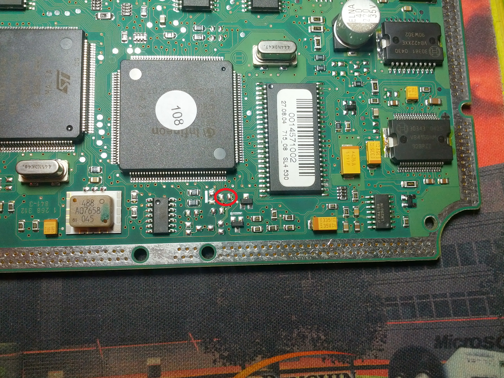 |
|
|
|
|
Logged
|
|
|
|
Matthewest91
Full Member
Karma: +0/-4
Offline
Posts: 109
|
|
« Reply #26 on: August 05, 2024, 05:41:12 AM »
|
|
|
You are a lucky man. Your board is very easy to put in bootmode. Just short these two pads on powerup for 2s. The ECU is now in bootmode. This is the b6 s4. Ecu. I was able to get this one in boot mode. It’s the b7 s4 that’s a bit more involved Awesome to have more than one solution. Thanks . Sent from my iPhone using Tapatalk |
|
|
|
|
Logged
|
|
|
|
Matthewest91
Full Member
Karma: +0/-4
Offline
Posts: 109
|
|
« Reply #27 on: August 05, 2024, 06:23:14 AM »
|
|
|
you have the jumper on the wrong side of the resistor, look at the picture you posted closer
You talking about the jumper needing to be on the left side of the yellow one on the ecu board ? Sent from my iPhone using Tapatalk |
|
|
|
|
Logged
|
|
|
|
Matthewest91
Full Member
Karma: +0/-4
Offline
Posts: 109
|
|
« Reply #28 on: August 05, 2024, 06:30:47 AM »
|
|
|
you have the jumper on the wrong side of the resistor, look at the picture you posted closer
This is how I had the jumper, I don’t know what you mean.  Sent from my iPhone using Tapatalk |
|
|
|
|
Logged
|
|
|
|
Matthewest91
Full Member
Karma: +0/-4
Offline
Posts: 109
|
|
« Reply #29 on: August 05, 2024, 07:28:15 AM »
|
|
|
Possibly the 1kojm resistor is the problem?
Should try without it
Sent from my iPhone using Tapatalk
|
|
|
|
|
Logged
|
|
|
|
|
