Pages: [1]
Author Topic: 4D0 907 555 AH with and without PES G1 Tune  (Read 14067 times)
keithwbloom
Jr. Member
**

Karma: +0/-1
Offline Offline

Posts: 43


« on: February 12, 2013, 09:28:23 PM »

I have several 2.8L AHA ECUs for A4 Quattro 5-speeds to provide bins from if someone can help me with the pinouts on this connector:


The bench harness I have is for later ME7.1 ATQ ECU, but I would love to provide these for everyones' reference and also to see the differences between the stock NA maps and the tuned supercharged maps as created by PES.

 Wink

Logged
ddillenger
Hero Member
*****

Karma: +641/-21
Offline Offline

Posts: 5640


« Reply #1 on: February 12, 2013, 09:30:25 PM »

You can't read those, just write. They're M5.9.2 vs ME7.1 Sad

Here's an original read though, I desoldered and read it in a chip reader.

I would be willing to remove the eprom and read it/send you the file if you want to send me the ecus. Having those files would be pretty helpful as tuning solutions don't really exist (I'm referring to the 2.8 m5.9.2, not 5.9.2 in general).
« Last Edit: February 12, 2013, 09:47:56 PM by ddillenger » Logged

Please, ask all questions on the forums! Doing so will ensure the next person with the same issue gets the opportunity to learn from your experience!

Email/Google chat:
DDillenger84(at)gmail(dot)com

Email>PM
k0mpresd
Hero Member
*****

Karma: +146/-54
Offline Offline

Posts: 1655


« Reply #2 on: February 12, 2013, 09:43:31 PM »

this is the pinout btw, but yep, youre not reading those without some soldering involved.

Logged
ddillenger
Hero Member
*****

Karma: +641/-21
Offline Offline

Posts: 5640


« Reply #3 on: February 12, 2013, 09:46:30 PM »

Worth noting!

If you want to connect via vcds/etc on the bench, leave pin 43 disconnected. That's the programming pin and should only be powered up if you plan on writing to the ecu. If you attempt to connect with a scanner while pin 43 is powered, you will receive an error along the lines of "too many communication errors to continue".

That, and hardware wise they're compatible with m3.8.3 and vice versa. The flash from one will work on the other.
« Last Edit: February 12, 2013, 09:49:23 PM by ddillenger » Logged

Please, ask all questions on the forums! Doing so will ensure the next person with the same issue gets the opportunity to learn from your experience!

Email/Google chat:
DDillenger84(at)gmail(dot)com

Email>PM
keithwbloom
Jr. Member
**

Karma: +0/-1
Offline Offline

Posts: 43


« Reply #4 on: February 13, 2013, 06:19:52 AM »

yep, youre not reading those without some soldering involved.

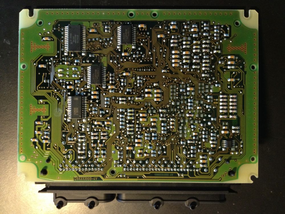
Not a stranger to de-soldering and reading/writing to IC/EEPROMs. Had to do so to resuscitate my W8 FIS cluster. Have a hot air rework station now. I guess I'll open them up and have a look for the likely culprits. Assuming the EEPROM will be a small chip like the cluster and ME7.x ECUs. What kind of chip am I looking for to read flash info from?

Top of the PCB


Bottom of the PCB:

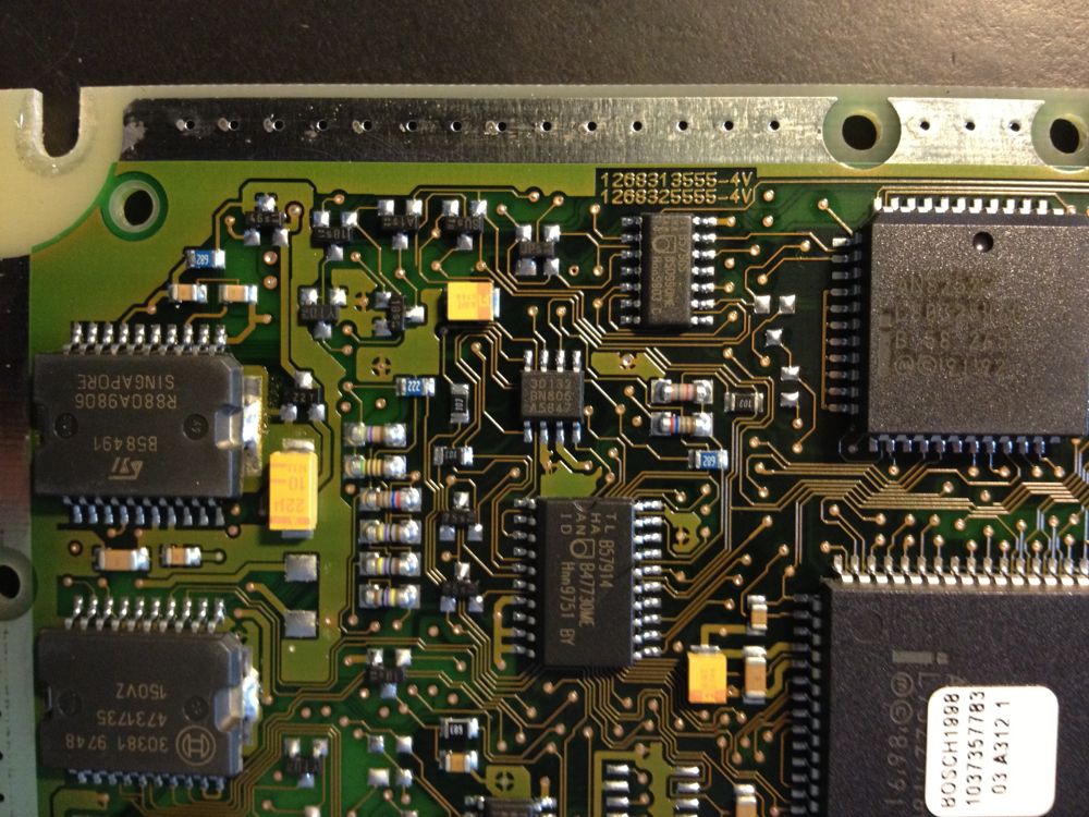
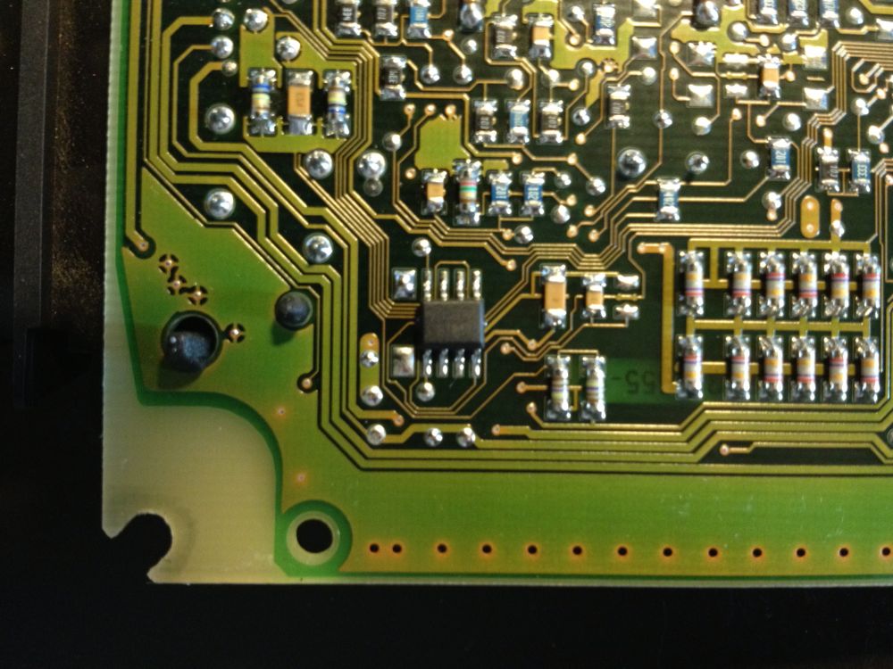
For EEPROM, these two are the likely candidates -

This one is on the top of the PCB, and the markings are 30132 BN806 A5847:

This one is on the bottom of the PCB, and the markings are very difficult to read:
« Last Edit: February 13, 2013, 06:46:00 AM by keithwbloom » Logged
ddillenger
Hero Member
*****

Karma: +641/-21
Offline Offline

Posts: 5640


« Reply #5 on: February 13, 2013, 08:14:26 AM »

The tune is stored on the chip marked 29f400bb (or 29f200bb depending on the year)

The immo/adaptations will be on a 24c02
Logged

Please, ask all questions on the forums! Doing so will ensure the next person with the same issue gets the opportunity to learn from your experience!

Email/Google chat:
DDillenger84(at)gmail(dot)com

Email>PM
keithwbloom
Jr. Member
**

Karma: +0/-1
Offline Offline

Posts: 43


« Reply #6 on: February 13, 2013, 10:18:17 AM »

The tune is stored on the chip marked 29f400bb (or 29f200bb depending on the year)

The immo/adaptations will be on a 24c02

At least on this board, the flash chip is a 29f200ab, c. 1993 from AMD (top right center of top PCB view.)

I am definitely going to need a bigger chip reader for that format.  Shocked

Since I am going to probably have to purchase or create a USB reader for that format, I imagine while I am shopping for components I could get some extra 29f800 ICs with through hole leads and put a socket on one or both of my ATQ PCBs. Could make swapping tunes a bit easier. Or perhaps that is over engineering. Wink
Logged
ddillenger
Hero Member
*****

Karma: +641/-21
Offline Offline

Posts: 5640


« Reply #7 on: February 13, 2013, 10:25:53 AM »

There's no need to socket an me7. As for socketing the ecu, the psop44 sockets I've seen are good for roughly 10 insertions before needing to be replaced.

If you want to read those chips without buying anything, just desolder them, and install them on an me7. Read the files in bootmode, and you're good to go (Kompresd's idea, I've used it and it does indeed work).

http://www.chip-service.de/product_info.php?info=p191_PSOP44%20Socket%20Meritec.html

http://www.chip-service.de/product_info.php?info=p190_PSOP44%20Socket%20Yamaichi.html

I've socketed a few TCU's for experimentation, but only because I don't have an alternative method to flash the chips while still installed on the tcu.
Logged

Please, ask all questions on the forums! Doing so will ensure the next person with the same issue gets the opportunity to learn from your experience!

Email/Google chat:
DDillenger84(at)gmail(dot)com

Email>PM
keithwbloom
Jr. Member
**

Karma: +0/-1
Offline Offline

Posts: 43


« Reply #8 on: February 13, 2013, 10:34:02 AM »

If you want to read those chips without buying anything, just desolder them, and install them on an me7. Read the files in bootmode, and you're good to go (Kompresd's idea, I've used it and it does indeed work).

Brilliant!

Logged
Pages: [1]
  Print  
 
Jump to:  

Powered by SMF 1.1.21 | SMF © 2015, Simple Machines Page created in 0.025 seconds with 18 queries. (Pretty URLs adds 0s, 0q)