|
ktm733
|
 |
« on: April 27, 2015, 09:48:14 PM »
|
|
|
Can someone help me in building a bench harness? I looked at another topic yet I can seem to be able to read ecu info or even communicate. Maybe I wired it wrong.
|
|
|
|
|
 Logged
|
|
|
|
|
ktm733
|
 |
« Reply #1 on: April 28, 2015, 08:43:48 PM »
|
|
|
nobody?
|
|
|
|
|
 Logged
|
|
|
|
|
ddillenger
|
 |
« Reply #2 on: April 28, 2015, 09:10:18 PM »
|
|
|
what do you need? This is all over ze interwebz.  |
|
|
|
|
 Logged
|
Please, ask all questions on the forums! Doing so will ensure the next person with the same issue gets the opportunity to learn from your experience!
Email/Google chat:
DDillenger84(at)gmail(dot)com
Email>PM
|
|
|
|
ktm733
|
 |
« Reply #3 on: April 28, 2015, 09:14:50 PM »
|
|
|
Mistaking switched can high and low urghh!! but we got a read, repeat we have a read haha
|
|
|
|
|
 Logged
|
|
|
|
Mechsoldier
Full Member
  
Karma: +5/-11
 Offline Offline
Posts: 106
|
 |
« Reply #4 on: May 25, 2015, 12:48:38 PM »
|
|
|
What would this be used for? Like Galletto? Can Boot mode be done with this? Because I've been opening the ECM up
|
|
|
|
|
 Logged
|
|
|
|
|
ktm733
|
 |
« Reply #5 on: May 25, 2015, 01:19:42 PM »
|
|
|
i actually can flash it butttt you need to delete immobilizer first then you can flash on the bench or i can flash through obd2 port actually and read.
|
|
|
|
|
 Logged
|
|
|
|
turbo944s2
Full Member
  
Karma: +1/-0
 Offline Offline
Posts: 59
|
 |
« Reply #6 on: January 30, 2017, 01:24:46 PM »
|
|
|
I'm having a hard time getting my harness to work.
Here is how I have it connected
ECU # 6 #92, #87 to the ac adapter positive and the OBD2 Connector Pin 16
ECU # 2 , pin 4 on the OBD2 connector.
Can HI to Can HI from the ecu to OBD2 Pin 6 to 68
Can Low to Can Lo from the ecu to OBD2 Pin 14 to 67
Kline 86 to Pin 7
Still no communication any suggestions?
|
|
|
|
|
 Logged
|
|
|
|
Sn0w3y
Newbie

Karma: +0/-0
 Offline Offline
Posts: 17
|
 |
« Reply #7 on: February 06, 2022, 07:10:39 PM »
|
|
|
Bro same problem here  |
|
|
|
|
 Logged
|
|
|
|
Geomeo
Full Member
  
Karma: +12/-2502
 Offline Offline
Posts: 163
|
 |
« Reply #8 on: February 06, 2022, 07:40:04 PM »
|
|
|
Try searching google images for bosch me 9.1 pinout. Plenty pictures and they are all nicely colored.
|
|
|
|
|
 Logged
|
|
|
|
garagebuilt
Newbie

Karma: +5/-0
 Offline Offline
Posts: 15
|
 |
« Reply #9 on: May 04, 2022, 07:52:23 AM »
|
|
|
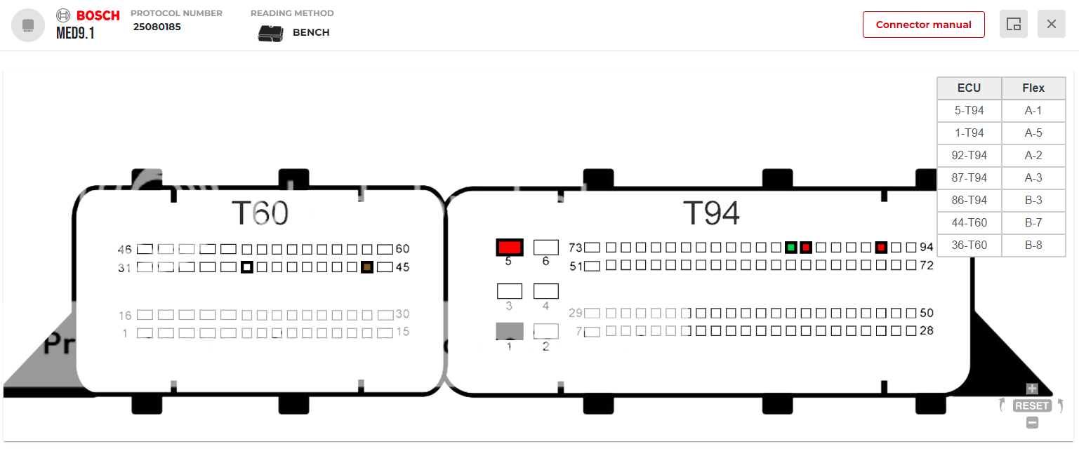
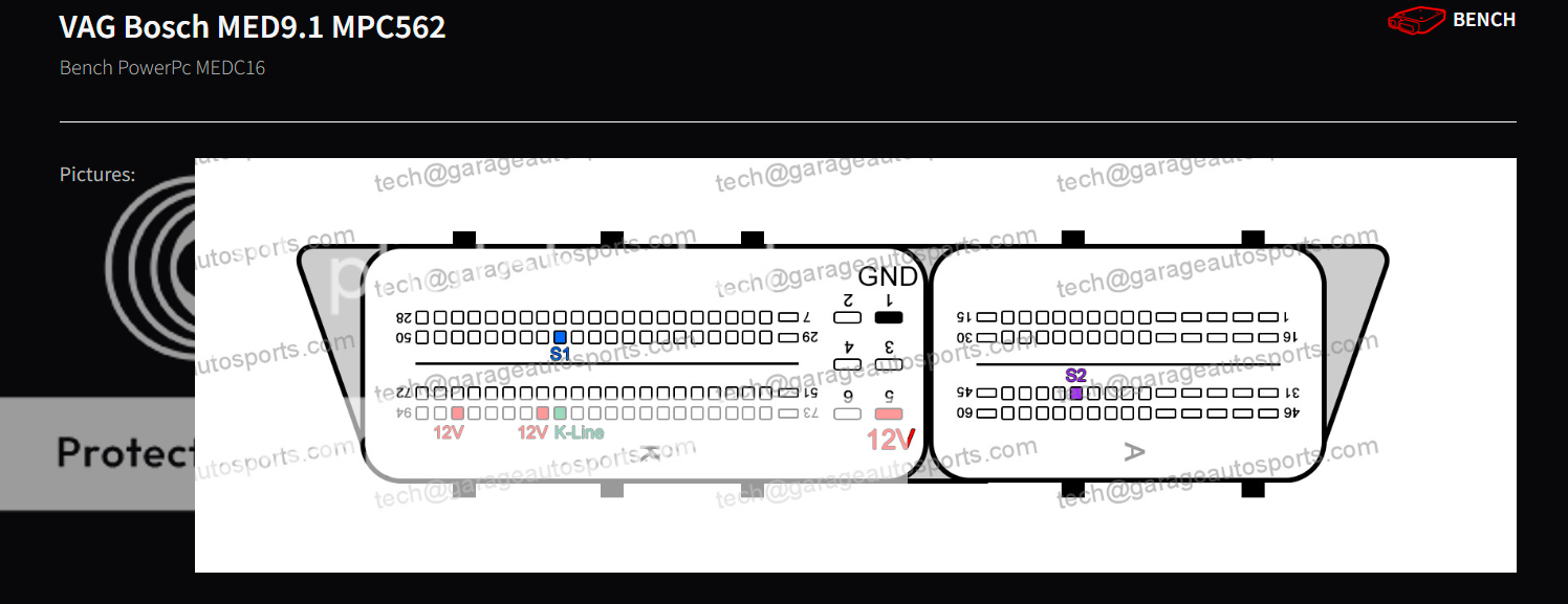
Here are 2 connection possibilities based on which tool is being used:  A1/A2/A3 +12v A5 Ground B3 K-line B7/B8 S1/S2 OR (**ECU is upside down in this image take note**)  12V/Gnd/K-line are all in the same places in this version, but the security connections are moved. I've been using both of these connections methods with success for years with both Magic Motorsport and bFlash, these are not so much universal connections but hopefully the positions help. |
|
|
|
« Last Edit: May 04, 2022, 08:01:14 AM by garagebuilt »
|
 Logged
|
|
|
|
|
aef
|
 |
« Reply #10 on: May 04, 2022, 11:35:05 PM »
|
|
|
Dont mix things here.
Back in the days Bench was OBD on the Table.
Today, and what your pictures show, is the Bosch Service Mode with the S1/S2 Signal going into the ecu.
|
|
|
|
|
 Logged
|
|
|
|
garagebuilt
Newbie

Karma: +5/-0
 Offline Offline
Posts: 15
|
 |
« Reply #11 on: July 20, 2022, 04:31:33 PM »
|
|
|
Dont mix things here.
Back in the days Bench was OBD on the Table.
Today, and what your pictures show, is the Bosch Service Mode with the S1/S2 Signal going into the ecu.
Valid observation! I started tuning with a Kess/Ktag setup and went from there, so never played around with a bench OBD setup. Well hopefully those help someone out  |
|
|
|
|
 Logged
|
|
|
|
kamold
Newbie

Karma: +0/-0
 Offline Offline
Posts: 9
|
 |
« Reply #12 on: August 26, 2022, 10:44:18 PM »
|
|
|
Hi guys,
I'm trying to do a boot mode read of an MED9.1 VAG ecu using PCMFlash.
I just bought the module 77 for these ECUs however I do not have the official harness.
I have the connection diagrams similar to above (there are a few different variants of which GPT pins to use, tried them all).
Was hoping to get this going with a home-brew connection as it will take a few weeks for a harness to arrive.
I have a powerbox and cable, so power and KLine are taken care of. Connecting to PCMFlash with Tactrix OPenport which I've been using fine with other modules like MED17 OBD, TCU direct connects etc.
I think I'm stuck on the GPT(security) pins. The powerbox has a switchable 3.3/5v interface that I've used to provide the S1/S2 connections.
Have tried both 3.3v and 5v but so far without success in even identifying the ECU.
Can connect on the bench over the CAN pins and see the ECU ok with VCDS.
Just hoping someone might be able to assist with identifying what voltage is required on the GPT pins, and does it also require an inline capacitor to generate a frequency or just constant voltage?
Thanks in advance.
|
|
|
|
|
 Logged
|
|
|
|
|
prj
|
 |
« Reply #13 on: August 27, 2022, 04:13:46 AM »
|
|
|
Why don't you ask support?
|
|
|
|
|
 Logged
|
|
|
|
kamold
Newbie

Karma: +0/-0
 Offline Offline
Posts: 9
|
 |
« Reply #14 on: August 27, 2022, 02:08:30 PM »
|
|
|
Yeah I'll ask in the forum, suspect I'll just get the 'use the official harness' answer
|
|
|
|
|
 Logged
|
|
|
|
|