Pages: 1 [2]
Author Topic: BDM100 > MED9.1 pinout conversion  (Read 52158 times)
h100vw
Jr. Member
**

Karma: +0/-0
Offline Offline

Posts: 34


« Reply #15 on: August 03, 2015, 11:27:16 PM »

Thanks for those replies fellas. Tried all kinds of combinations of connection order and the same result.

http://www.digital-kaos.co.uk/forums/showthread.php/278197-First-start-BDM100-%28China%29-problem

So I found this after finding the Dimsport software and trying that. It gives the same error. So I got to wondering if the ECU isn't seen by the BDM box?

When you click "ON" does the ECU respond very quickly to some communication attempt, which allows you to continue?

Anyway, I have buzzed the cable end to end and find that there's a few pins not connected. Probing the socket with a piece of lockwire, the bad sockets feel as though there's nothing in there. Hence the open circuit.

I can go to a local place tomorrow and get some new plugs.Just wondering if there's a valid reason that some of the wires might not run end to end.

I think it's bad manufacture.

Cheers

Gavin


PS I just took on of the sockets apart and there's only 6 wires out of the 10 that could be working. Is that correct?
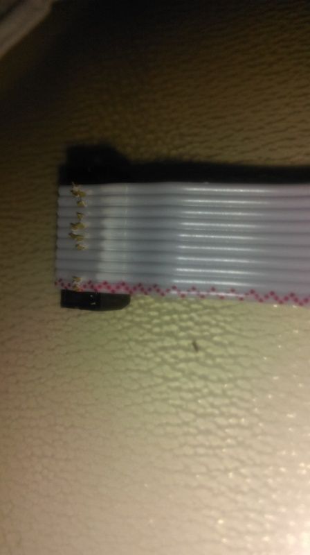
« Last Edit: August 04, 2015, 01:00:19 AM by h100vw » Logged
vwaudiguy
Hero Member
*****

Karma: +53/-37
Offline Offline

Posts: 2024


« Reply #16 on: August 04, 2015, 10:50:12 AM »

a lot of the times it has to do with the order you plug in the plugs.

What is the best order?
Logged

"If you have a chinese turbo, that you are worried is going to blow up when you floor it, then LOL."
k0mpresd
Hero Member
*****

Karma: +146/-54
Offline Offline

Posts: 1655


« Reply #17 on: August 04, 2015, 11:00:13 AM »

What is the best order?

never really tried to figure it out. just sort of plug it in and if it works, great, if not, unplug and replug until it does.
at one point in time i had soldered a little led on to the china 1:1 adapter that would illuminate when the bdm sent 12v/ground.
it would pulse if its sending power but doesnt connect to ecu (bad adapter > ecu connection) or not pulse at all even though it was clicking (not sending 12v).
Logged
h100vw
Jr. Member
**

Karma: +0/-0
Offline Offline

Posts: 34


« Reply #18 on: August 04, 2015, 10:07:08 PM »

ddilenger checked his lead and found it was 10 by 10. So I have bought new headers to fit on my cable. I'll update over the next couple of days if that works or not.

Cross your fingers please~ Grin
Logged
h100vw
Jr. Member
**

Karma: +0/-0
Offline Offline

Posts: 34


« Reply #19 on: August 04, 2015, 11:58:22 PM »

New headers fitted, buzzed the cable out and only one of the old headers is actually bad. So I am guessing it was a manufacturing fault. Just need to get my mate back around to try and read it again.

Logged
h100vw
Jr. Member
**

Karma: +0/-0
Offline Offline

Posts: 34


« Reply #20 on: August 07, 2015, 03:29:46 PM »

So the news is that the cable needs all 10 pins connecting at both ends. With new header fitted at $3AUD. The job is now done. Thanks to Daz for checking his cable out to confirm mine was different.

 Grin
Logged
birchbark506
Sr. Member
****

Karma: +11/-11
Offline Offline

Posts: 414


« Reply #21 on: July 29, 2016, 08:29:01 PM »

Can you show a picture of the right pin lay out on cable I think my cable is revised looks like red wire is on pin 10 on my bdm100clone
Logged
h100vw
Jr. Member
**

Karma: +0/-0
Offline Offline

Posts: 34


« Reply #22 on: August 04, 2016, 02:29:25 PM »

Missed your question here mate. I'll do that when I get in from work.
Logged
eliotroyano
Hero Member
*****

Karma: +48/-8
Offline Offline

Posts: 825


« Reply #23 on: August 05, 2016, 07:25:47 PM »

I had same problem in the past with BDM100. Test every solder in interface box and also check board paths in BDM adapter. After almost 2 days doing lots of tests I found a path broken at pogo pins. It does not have connection.
This is the right pinout in MED9.1 board.

More info here --> https://www.drive2.ru/l/2429928/
Logged
birchbark506
Sr. Member
****

Karma: +11/-11
Offline Offline

Posts: 414


« Reply #24 on: August 06, 2016, 05:10:40 AM »

So use the pin out that is in this picture?
Logged
eliotroyano
Hero Member
*****

Karma: +48/-8
Offline Offline

Posts: 825


« Reply #25 on: August 06, 2016, 06:51:39 PM »

So use the pin out that is in this picture?

Yes for a BDM100.
Logged
IamwhoIam
Hero Member
*****

Karma: +52/-114
Offline Offline

Posts: 1070


« Reply #26 on: December 05, 2017, 08:47:42 AM »

I'm not sure who the tunners are?
Logged

I have no logs because I have a boost gauge (makes things easier)
Pages: 1 [2]
  Print  
 
Jump to:  

Powered by SMF 1.1.21 | SMF © 2015, Simple Machines Page created in 0.02 seconds with 17 queries. (Pretty URLs adds 0s, 0q)