Pages: [1] 2 3 ... 10
Author Topic: PID contoller calibration from square one  (Read 134707 times)
elRey
Hero Member
*****

Karma: +31/-1
Offline Offline

Posts: 565


« on: April 08, 2011, 08:40:00 AM »

Hey guys,

Can we get a how-to on calibrating the LDRPID from scratch? I mean from a clean slate.

First discovering duty <=> boost open loop
then duty linearization
and only then P I D components

?

i.e.
What needs to be set to get into the mode for open loop discovery of duty <=> boost relationship and duty linearization.

And then what are the steps of setting a specified duty, run car, and record boost maintained by that duty @ RPMs and then set another specified duty, repeat.

I'm finding the stock PID maps are way off when different wastegates (actuators) and more open exhausts are used. And just tweaking the PID maps are getting me no where fast.

Thanks,
Rey
Logged
TTQS
Guest
« Reply #1 on: April 12, 2011, 02:26:17 AM »

Hi.

Sounds like a tall order! The phrase "from square one" worries me because it is stated in the LDRPID module of the funktionsrahmen that this is done using an engine dynamometer in the laboratory using the Ziegler-Nichols tuning method (apparently a very good standard theoretical method of working out the necessary proportional, integral and derivative parameters). Presumably involving scores of hours work. This will, of course, be for a new engine design for which no prior art exists. For uprated variants of existing engines, I presume the engineers start with the existing control parameters as a baseline.

Somehow, I think that even an overview of the process is beyond us.

Doug
« Last Edit: April 13, 2011, 05:42:49 AM by TTQS » Logged
TTQS
Guest
« Reply #2 on: April 12, 2011, 02:35:59 AM »

...previous post continued because of truncation:

I did a quick Google search and there is a very short summary of the Ziegler-Nichols tuning rules on Wikipedia which references the original source here:

http://www.mstarlabs.com/control/znrule.html

The Ziegler-Nichols method apparently results in aggressive gain and overshoot which probably explains why we all see overshoot of boost on the stock maps! The table gives parameters for different states including 'no overshoot'. Worth a look but I've never used it myself in any context even though I'm surrounded by PID controllers at work.
« Last Edit: April 13, 2011, 05:42:32 AM by TTQS » Logged
carlossus
Sr. Member
****

Karma: +38/-0
Offline Offline

Posts: 394

Leon Curpa Stg1+


« Reply #3 on: April 12, 2011, 05:09:32 AM »

Two years ago I wrote a simple PID control loop for a motorised mass with encoder feedback. I used this method to tune it and I was amazed how easy it was.

The biggest problem with attempting this with a vehicle is that the first step is to deliberately set the loop to oscillate around the setpoint so that you can measure its period. In a lab with position or velocity as the setpoint this is easy, but when it is boost pressure you would need to hope one oscillation period was somewhat less than the time it takes to redline. You would need several oscillations to be sure you got the period accurately. Plus you have other inputs to the control loop that you can't control (you'd have to disable a lot of ME7 protections to allow this behaviour).

I have a feeling that this method would yield a significantly worse result that the stock PID tuning as a starting point.

In my opinion it would be far better to get a really good understanding of each term, then tweak each variable based on iterative testing.
Logged
nyet
Administrator
Hero Member
*****

Karma: +604/-166
Offline Offline

Posts: 12232


WWW
« Reply #4 on: April 12, 2011, 01:30:33 PM »


I have a feeling that this method would yield a significantly worse result that the stock PID tuning as a starting point.


I agree Sad

To make matters even more difficult, tuning a BRAND new PID is going to be difficult if you are trying to tune near max MAP readings ....
« Last Edit: April 12, 2011, 01:32:10 PM by nyet » Logged

ME7.1 tuning guide (READ FIRST)
ECUx Plot
ME7Sum checksum checker/corrrector for ME7.x

Please do not ask me for tunes. I'm here to help people make their own.

Do not PM me technical questions! Please, ask all questions on the forums! Doing so will ensure the next person with the same issue gets the opportunity to learn from your experience.
elRey
Hero Member
*****

Karma: +31/-1
Offline Offline

Posts: 565


« Reply #5 on: April 12, 2011, 03:15:48 PM »

OK. I agreed with everythign said.

how about starting simple. Duty linearization.
Logged
nyet
Administrator
Hero Member
*****

Karma: +604/-166
Offline Offline

Posts: 12232


WWW
« Reply #6 on: April 12, 2011, 03:50:17 PM »

OK. I agreed with everythign said.

how about starting simple. Duty linearization.

I'd probably put the wastegate + n75 on a bench, apply cracking pressure + a few psi to the n75, and see how far the gate opens for a given duty.

Maybe get a stock wg and compare.
Logged

ME7.1 tuning guide (READ FIRST)
ECUx Plot
ME7Sum checksum checker/corrrector for ME7.x

Please do not ask me for tunes. I'm here to help people make their own.

Do not PM me technical questions! Please, ask all questions on the forums! Doing so will ensure the next person with the same issue gets the opportunity to learn from your experience.
elRey
Hero Member
*****

Karma: +31/-1
Offline Offline

Posts: 565


« Reply #7 on: April 13, 2011, 07:36:12 PM »

How far a wastegate moves is not always linear to boost held in a complete system.
Or even the same throughout the RPM range.

What I did:

set CWMDAPP = 8

set all cells in KFLDRAPP = 0
ran several runs and logged actual boost thru entire RPM range
set all but lower 3 PED% rows = 10
ran several runs and logged actual boost thru entire RPM range
set all but lower 3 PED% rows = 20
ran several runs and logged actual boost thru entire RPM range
set all but lower 3 PED% rows = 30
ran several runs and logged actual boost thru entire RPM range
repeat thru 80%

For each RPM axis value in KFLDRL I traced the logged boost.
SO, I end up with a map (in excel) with same axis as KFLDRL but with z values of actual boost at that duty/RPM node. (not linear)

I then made another map than was linear from 0% to 80% (last duty I had real data for)
for each RPM.

I then cross reference the linear values in in the non-linear map and interpolated.
The value I ended up with went into the KFLDRL map.

I'll post pictures later.

Logged
judeisnotobscure
Sr. Member
****

Karma: +38/-10
Offline Offline

Posts: 379


« Reply #8 on: April 13, 2011, 07:47:37 PM »

nice  work... I'm in to see some data.
Logged

I have a b5 s4
but i just want to dance.
nyet
Administrator
Hero Member
*****

Karma: +604/-166
Offline Offline

Posts: 12232


WWW
« Reply #9 on: April 13, 2011, 08:04:14 PM »

awesome i'd like to see that too!
Logged

ME7.1 tuning guide (READ FIRST)
ECUx Plot
ME7Sum checksum checker/corrrector for ME7.x

Please do not ask me for tunes. I'm here to help people make their own.

Do not PM me technical questions! Please, ask all questions on the forums! Doing so will ensure the next person with the same issue gets the opportunity to learn from your experience.
elRey
Hero Member
*****

Karma: +31/-1
Offline Offline

Posts: 565


« Reply #10 on: April 14, 2011, 01:49:35 PM »

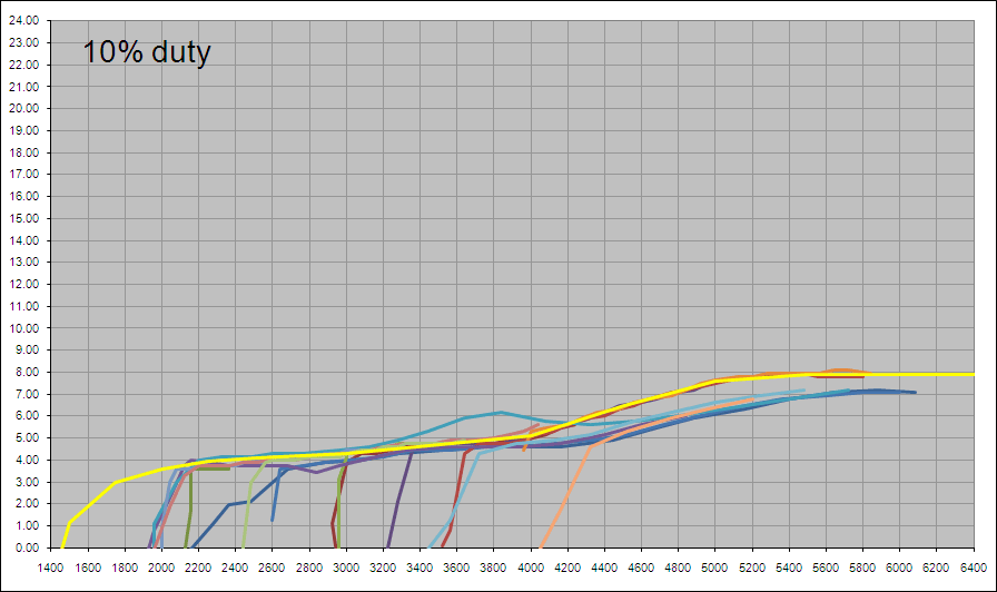
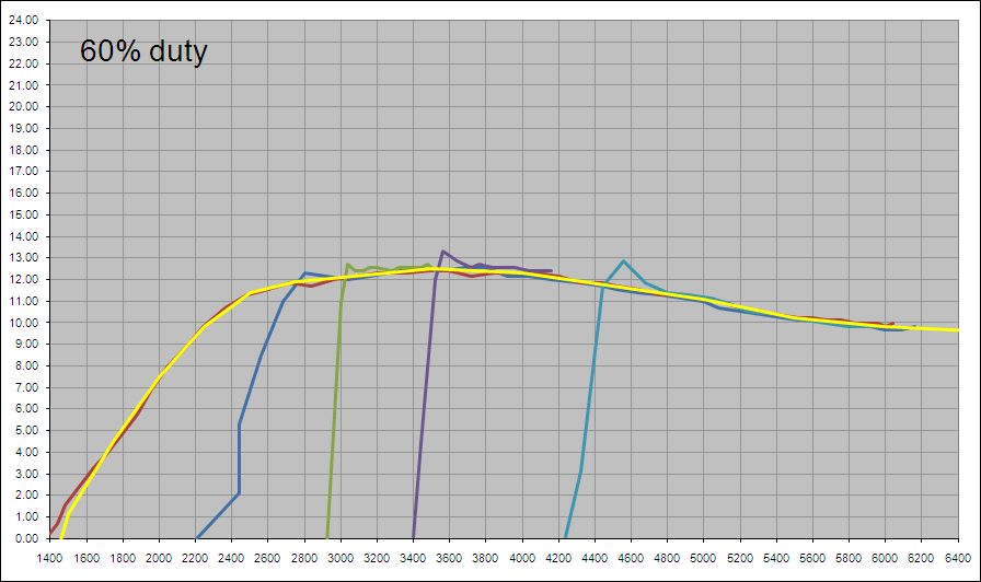
You can see I had to make several runs in different gears to cover the whole RPM range.
then trace (yellow) the boost curve that emerges from the compiled runs.


logged runs from KFLDRAPP = 0
traced at same RPM points as KFLDRL in yellow (table below)


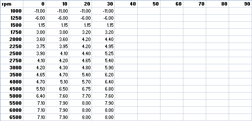
logged runs from KFLDRAPP = 10 (leaving lower 3 PED% rows =0)
traced at same RPM points as KFLDRL in yellow (table below)


logged runs from KFLDRAPP = 20 (leaving lower 3 PED% rows =0)
traced at same RPM points as KFLDRL in yellow (table below)


logged runs from KFLDRAPP = 30 (leaving lower 3 PED% rows =0)
traced at same RPM points as KFLDRL in yellow (table below)


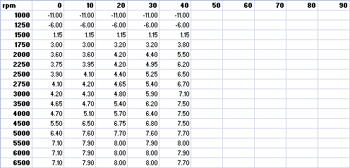
logged runs from KFLDRAPP = 40 (leaving lower 3 PED% rows =0)
traced at same RPM points as KFLDRL in yellow (table below)


logged runs from KFLDRAPP = 50 (leaving lower 3 PED% rows =0)
traced at same RPM points as KFLDRL in yellow (table below)


logged runs from KFLDRAPP = 60 (leaving lower 3 PED% rows =0)
traced at same RPM points as KFLDRL in yellow (table below)


logged runs from KFLDRAPP = 70 (leaving lower 3 PED% rows =0)
traced at same RPM points as KFLDRL in yellow (table below)


logged runs from KFLDRAPP = 80 (leaving lower 3 PED% rows =0)
traced at same RPM points as KFLDRL in yellow (table below)

« Last Edit: April 14, 2011, 02:12:55 PM by elRey » Logged
elRey
Hero Member
*****

Karma: +31/-1
Offline Offline

Posts: 565


« Reply #11 on: April 14, 2011, 02:01:21 PM »

The completed duty<->boost table above give me this:


Notice how non-linear the boost response to duty.

Then I carry down the 0% and 80% data columns and calculate the linear boost per duty steps. This is how.
For each RPM node find the delta boost between 0% duty and 80% (or highest duty you log).
Then using the 0% and 80% columns, map the linear boost for each step between them.
So, for 0 to 80 by increments of 10 there are 8 steps. I take the delta found for each RPM and multiple it by the increments of 8 steps + the lowest boost (0%).


Once I have this linear table I get this:
Logged
elRey
Hero Member
*****

Karma: +31/-1
Offline Offline

Posts: 565


« Reply #12 on: April 14, 2011, 02:12:23 PM »

Now I use the values for the linear boost table and look up/interpolate  where it would fall on the non-linear table to duty.


But this is really done by an excel formula:


Once I do this lookup/interpolation for all nodes I get the final KFLDRL values:


vs stock:


Granted this is not 100% accurate because the true boost response is not a straight line between each duty node, but I doing the lookup/interpolation against it as if it were straight. You could build the first table with more duty nodes for a more accurate calibration, but that requires more KFLDRAPP change/run log sessions.
« Last Edit: April 14, 2011, 02:56:48 PM by elRey » Logged
judeisnotobscure
Sr. Member
****

Karma: +38/-10
Offline Offline

Posts: 379


« Reply #13 on: April 14, 2011, 02:23:50 PM »

amazing work... thank you so much for sharing.  What turbos and waste gates did you do this with?
Logged

I have a b5 s4
but i just want to dance.
elRey
Hero Member
*****

Karma: +31/-1
Offline Offline

Posts: 565


« Reply #14 on: April 14, 2011, 02:28:15 PM »

Simple K04 replace for a B5 passat 1.8T. Internal wastegate with actuator.

But stock PID maps could not hold boost steady at all. Since I was going to rework PID maps I thought it wise to make sure KFLDRL was calibrated correctly. I'll see if  I can post some before and after request boost vs actual boost graphs.
Logged
Pages: [1] 2 3 ... 10
  Print  
 
Jump to:  

Powered by SMF 1.1.21 | SMF © 2015, Simple Machines Page created in 0.024 seconds with 16 queries. (Pretty URLs adds 0.001s, 0q)